Model-based engineering reduces construction cost at YIT Corporation
Introduction
The largest construction company in Finland, the YIT Corporation uses model-based tools for construction-process integration. The first fielded solution, a Cost and Value Engineering (COVE) application (see figure 1.) has already provided significant advantages.
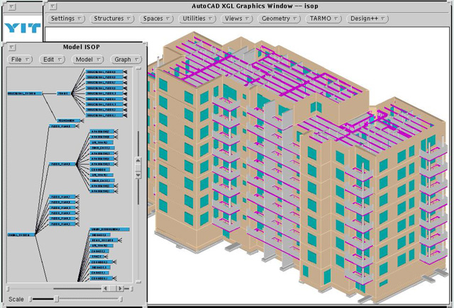
Figure 1. Courtesy of YIT Corporation: A Cost and Value Engineering utilizing the integrated Design++® and AutoCAD environment.
Mr. Jarmo
Laitinen, Information Technology Development Manager of
the YIT Corporation, explains:
“The model-based system's closely integrated approach promises savings of up to 20 percent of the
total project costs. Finland is at the forefront of applying information technology in integrated construction. So far, builders have failed to recognize the full potential of information technology. Basically, they've simply transferred their old manual routines onto PCs. The result of our new approach at YIT is a “virtual building” that in a very short time enables us to investigate and demonstrate the effect of alternate design solutions. This not only reduces weeks of design lead time to hours but also gives the client a clear idea of his available choices - and what effect these will have on the final building.”
YIT is partnering with Design Power Europe (DPE), a subsidiary of Design Power, Inc., in developing the model-based engineering solutions. While DPE provides the basic tool set and its model reasoning functionality, YIT is responsible for most of the knowledge about construction methods, cost information and other required construction expertise.
Improving the construction process through integration
Intra-enterprise Integration
The model-based technology used in the COVE project lends itself very well to integrating various parts of the work processes. A logical model that includes company work process rules retains required relationships between modeled systems and components and allows them to change as the models change during the progress of the building project. The free flow of information from one discipline to others is ensured by these relationships. This information flow, in itself, will significantly reduce project cost through faster implementation and fewer mistakes due to missing information.
Inter-enterprise integration
YIT is a real estate developer and construction company. It cooperates intimately with architects, engineers, HVAC companies and others. Early in the model-based solution project, YIT created a development consortium where its key partners joined in the project to further reap the benefits of inter-company integration. As part of this effort DPE developed a method of sharing product models to benefit all partners
The COVE solution is just the first part of YIT’s master plan to cover the whole life-cycle of buildings, which are its main products of.
The Cost and Value Engineering (COVE) solution
The purpose of the COVE solution is to provide YIT with a fast way to evaluate construction solutions for building designs while at the same time providing accurate cost estimates for each alternative. Standard industry practices are too time consuming to allow such optimization; the first selected method is usually “ cast in concrete”. Not only is this an internal cost reduction tool, but a marketing tool as well. By taking the client as a participant in design decisions while considering their impacts on cost, YIT significantly increases its ability to win the project.
The COVE solution starts with the input of an architect's design. YIT takes this design, either in paper form or as CAD files, and inputs it into the system by identifying the building elements (like walls doors, windows and spaces) and their dimensions. The input is mainly through the integrated CAD and building-component-specific dialogs (as exemplified in figure 2).
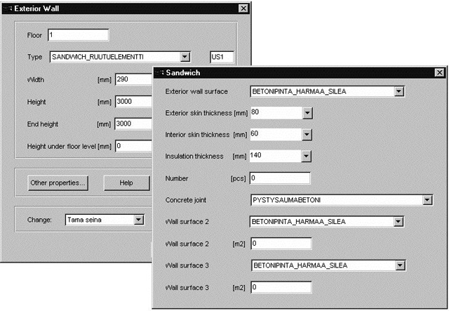
Figure 2. User Interfaces for creating exterior wall elements.
While input is taking place, the underlying knowledge-based engineering tool, Design++®, automatically creates a logical model containing the identified elements and any other element that YIT’s configuration, selection and sizing rules require. The system also creates a 3D model of the input components and places them into a 3D model of the entire building (see figure 1.) This model is important both for verifying the completeness of the data input and for observing the effects of subsequent change proposals.
Figures 3 and 4 show examples of additional user-interfaces for adding rooms and then adding non-bearing partition walls to the rooms.
Once the input is completed, rules in the logical model are fired to collect all suitable construction methods. The configured “virtual” building (the model) and the selected construction methods are then combined with the right details in a data base to define the “nuts-and-bolts” and labor details of each component to produce accurate cost estimates of the entire building project.

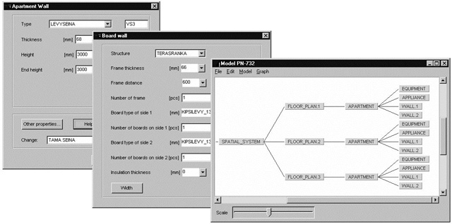
Figures 3 and 4. User Interface for creating rooms (3) and partition walls (4) and the corresponding states of the product model.
The real advantage of the system is realized when looking for better solutions. YIT’s planners can change component selections, material selections, and construction method selections for classes of systems and components or individual components. The effects on cost are immediately available. Thus YIT can work with clients to find the most cost-effective solution to meet their requirements in just hours.
The underlying tools
The Solution ArchitectureThe COVE solution consists of several interacting software tools (see figure 5). It is developed on top of the Design++ knowledge-based modeling environment by creating building-specific component and configuration objects the Design++ libraries.
User Interface |
Data Broker |
AutoCAD |
Building Model Building Libraries KBE Modeling Engine |
Solid RDB |
Figure 5. The system architecture integrates AutoCAD, database, the Design++ KBE engine and a solutions interface. While the building designs are input into the system, Design++ fetches appropriate components from these libraries and creates a logical model of the building. Geometric objects in the model communicate with AutoCAD to produce a 3-dimensional (3D) view of the building (see figure 1.). The model communicates with a Solid relational data base to marry the building components with their proper details. Communications between the various modules are facilitated by the Design++ C/API and a powerful Data Broker architecture. The system is controlled through the graphical user interfaces created with Design Power’s GUI Builder.
The CAD
YIT selected AutoCAD as the integrated CAD because of its widespread use within the architect and engineering companies and within YIT. AutoCAD is tightly integrated with the geometric objects in the modeling tool, Design++, with a seamless bi-directional link. Several 2-dimensional (2D) drawings are combined in a single AutoCAD file. A hierarchical structure of CAD layers helps users navigate through the logical model. The 3D building model is also created by Design++ in AutoCAD.
Design++ and the logical model
Design++ uses engineering rules (knowledge) to generate the required information. In the COVE solution the Logical Product Modeling Environment (LPME) of Design++ is used to model both the spatial and structural components of a building.
In creating a Design++ model, the following types of rules are typically used:
Configuration rules
These rules are used to determine what components are needed based on the functional
requirements, e.g., load bearing capacity.Selection rules
These rules are used to determine what types of components to use, for example, the type of wall between apartments.Sizing rules.
These rules are used to determine dimensions of specific components, for example the thickness
of a facade element.
The Design++ environment uses its Design Rule Language (DRL) to define rules and algorithms in the system. It includes a Dynamic Configurator (DC) which uses configuration rules defined with DRL. The included Intelligent Change Manager (ICM) is responsible for keeping the model consistent in all cases. When changes are made the ICM propagates the change only as far as is required. The ICM and the re-configuration capabilities of the DC are the primary enablers for the rapid “what-if” investigation of building solution alternatives.
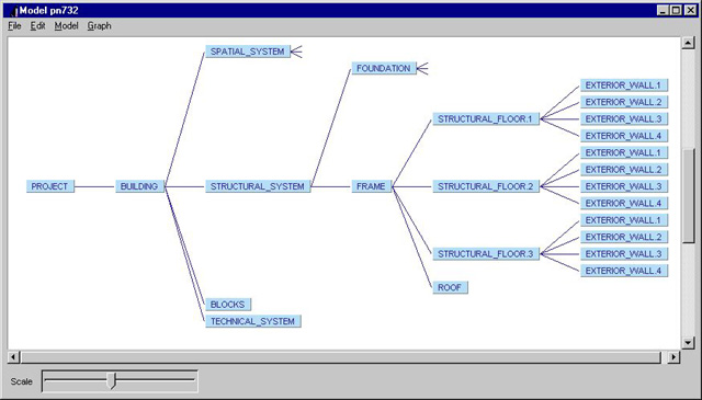
Figure 6. The hierarchical building product model is here shown as an object tree.
Rules may be modified individually at any time, allowing for an incremental and continuous upgrading of the system to incorporate new knowledge.
The logical building model in Design++ is organized in a hierarchical structure. For example, in figure 6, a building is comprised of several systems one of which is the structural system.
The structural system, in turn, consists of foundation and a frame. The frame is divided into floors, each of which contain load bearing walls.
The database
The high-performance database manages all the static information. It contains catalogue information for material, labor costs and detailed bills-of-material for model components. An example of such a bill of materials is seen in figure 7.
| Code | Name | Multiplier | Design++ Attribute Name | Unit |
|---|---|---|---|---|
| 1111 | wall panel | 1.1 | <Wall_area> | m2 |
| 2222 | nails | 0.05 | <weight> | kg |
| 3333 | Carpenter | 0.5 | <duration> | hours |
| etc. |
Figure 7. Typical database records showing wall components (example data).
The Model-Based advantage
Traditionally building design is document-based. In this traditional work-process model, the CAD system is the focus. This CAD-centric focus is limiting as only the design result is retained. Neither the design intent nor the design methodology is documented or incorporated. In a KBE-based system, the functional requirements are explicitly provided and the methods to fulfill these requirements in the form of configuration, selection and sizing rules are also incorporated in the system. The KBE-based system, then uses CAD in its traditional role to present the results graphically. In a building, one functional requirement is to bear loads. This requirement then drives a specific structural solution with correctly configured and sized (or selected) members, based on the size and type of loads it must carry and on the specific configuration of the builders.
The various systems and components may be interrelated in a logical model as they are in real life. In a CAD drawing the relations are implicit and typically only in 2D.
It is clear that a KBE system based on logical models enables solutions that could never be imagined in the CAD world.
Conclusion
YIT has already achieved significant advantages through the use of model-based engineering in the COVE solution. With its continuing effort in spreading this technology to other work processes, wherever there is an advantage to be found, YIT will stay ahead of the competition. YIT will also stay there for a long time because of its early initiative and its determination.
YIT Corporation: www.yitgroup.com